Safe Excavation knowledge
REQUIREMENTS BEFORE EXCAVATION
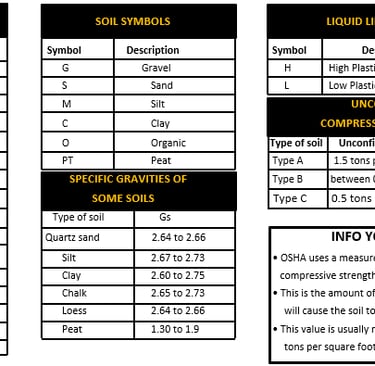
Type A
Cohesive soil with an unconfined, compressive strength of 1.5 tons per square foot (tsf) (144 kPa) or greater
Examples of Type A soils include:
Clay, silty clay, sandy clay, clay loam
Silty clay loam and sandy clay loam
cemented soils ex, caliche and hardpan
Type A soil cannot be: fissured; subjected to vibration from heavy traffic; pile driving or similar effects; Previously disturbed part of a sloped, layered system where the lavers dis into the excavation on a slope of 4 horizontal to 1 vertical (4H:1V) or greater, material subjected to other factors that would require it to be classified as a less stable material.
Type B
Cohesive soils with an unconfined compressive strength greater than 0.5 tut (48 kPa) but less than 15 tsf (144 kPa) Or granular cohesion less sods including: angular gravel. sit, sit loam, sandy loam and, in some cases, with the loam and sandy clay Ioam.
previously disturbed calls except those which would otherwise be classed as Type C soil.
soils that meet the unconfined compressive strength or cementation requirements of Type A soil but are fissured or subject to vibration
Dry unstable rock
material that is part of a shaped, layered system where the layers dip into the excavation on a slope less steep than 4 horizontal to 1 vertical (4H.1V), but only if the material would otherwise be classified as Type B.
Type C
Cohesive soil with an unconfined compression strength of 0.5 TSF (48 kPa) or less or granular soils including gravel, sand and loamy sand.
Submerged or soil from which water is freely seeping
submerged rock that is not stable
material in a sloped, layered system whore the inert dip into the excavation or have a slope of 4 horizontal
to 1 vertical (4H:1V) or steeper.
Note: Unconfined compressive strength refers to the land per unit
TERM ALERT!
Excavation; any operation in which earth, rock or other material in the ground is moved, removed or otherwise displaced by means of tools, equipment or explosives in any of the following ways: grading trenching. digging, ditching, drilling, auguring. tunneling, scraping, cable or pipe plowing and driving or any other way.
Excavator: any person, firm, owner, contractor, subcontractor, operator, association, corporation. utility, partnership, business trust, public agency. or other entity that, with their, or his/her, own employees or equipment performs any excavation.
Operator or Owner/Operator: any person, public agency, corporation, partnership, business trust or other entity that owns. Operates or maintains a subsurface installation.
Trench: a narrow underground excavation that is deeper than it is wide and no wider than 15 ft.
SUBSURFACE INSTALLATIONS
The excavator must determine the approximate location of subsurface installations expected to be encountered prior to opening an excavation.
Utility installations include sewer lines, fuel lines, electric lines, water lines, telephone lines, etc.
Excavation must not begin until:
the excavation area has been marked by the excavator
The excavator has received a positive response from all known owners/operators of subsurface installations withi the boundaries of the proposed project.
Owner /operator responses must confine the location of the installations and advise the excavator of those locations or inform the excavator that the owner/operator does not concrete a subsurface installation that would be affected by the excavation.
When excavation or boring operations approach the approximate location of subsurface installations, the exact location of the installations must be determined by safe and acceptable means to prevent damage.
While the excavation is open, subsurface installations must be protected, supported or removed as necessary to safeguard employees.
HIGH PRIORITY SUBSURFACE INSTALLATIONS
When the excavation is proposed within 10 ft. of a high priority subsurface installation.
The excavator must be notified by the facility caner/operator before the legal excavation start date and time.
There must be an onsite meeting involving the excavator and the subsurface installation owner /operator's representative to determine the action or activities required to verify the location of such installations.
High priority subsurface installations are:
High pressure natural gas pipelines with normal operating pressures greater than 415 Kpa gauge (60 psig)
Petroleum pipelines
Pressurized sewage pipelines
conductors or cables that have a potential to ground of 60,000 volts or more
hazardous materials pipelines that are potentially hazardous to employees or the public, if damaged.
SUBSURFACE INSTALLATIONS - DAMAGES
An excavator discovering or causing damage to a subsurface installation must immediately notify the facility owner/operator or contact the Regional Notification Center to obtain sub surface installation operator contact information immediately after which the excavator must notify the facility operator.
All breaks, leaks, ricks, dents, gouges, grooves or other damages to an installation's lines, conduits, coatings or cathodic protection must be reported to the subsurface installation operator.
If damage to a high priority subsurface installation results in the escape of any flammable, toxic or corrosive gas or liquid or endangers site, health or property, the excavator responsible must immediately notify 999.
The facility owner/operator must also be contacted.
DAILY INSPECTION
A competent person must inspect the trench and protective systems daily before the start of work and throughout the day as conditions change.
Competent person is defined as one who must demonstrate:
knowledge of the provisions pertaining to excavations,
knowledge of soil analysis as required in the provisions pertaining to excavations, trenches and earthwork
knowledge of the use of protective systems.
authority to take prompt corrective action on the job
ability to recognize and test for hazardous atmospheres
INFO YOU MUST KNOW
The Division of Occupational Safety and Health (DOSH). better known as Cal/OSHA, protects and improves the health and safety of working men and women in California and the safety of passengers riding elevators. Amusements rides and tramways by:
Setting and enforcing standards
Providing outreach, education and assistance
Issuing permits, licenses, certifications, registrations and approvals
BEFORE EXCAVATING
Obtain a permit from the DOSH if workers are required to enter an excavation that is 5 fi, or deeper.
Notify all Regional Notification Centers and any nonmember subsurface installation owners of the excavations at least 2 working days before starting excavation.
Only qualified persons must locate subsurface installations.
If excavation is within 10 ft. of a high priority subsurface installation, the owner and the excavator must meet onsite before excavation.
All subsurface installations revealed must be physically supported, protected or removed for employee safety.
CAL/OSHA PRELIMINARY DECISIONS
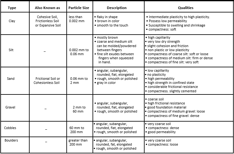
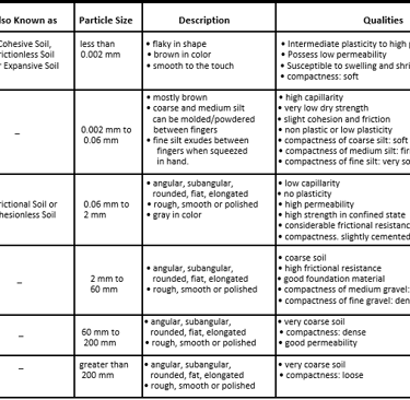
SOIL TYPES
TERM ALERT
Cemented soil: a soil in which the particles are hold together by a chemical agent so that a hand size sample cannot be crushed into powder or individual soil particles by finger pressure.
Cohesive soil: fine grained soil (clay) or soil with a high clay content, which has cohesive strength. It does not crumble, it can be excavated with vertical side slopes, it is plastic when moist, it is hard to break up when dry and exhibits significant cohesion when submerged.
Dry soil: soil that does not exhibit visible signs of moisture content
Fissured: a soil material that has a tendency to break along definite planes of fracture with little resistance or a material that exhibits open cracks (tension cracks) in an exposed surface.
Granular soil: coarse grained soil (gravel, sand or silt) with little or no clay content; has no cohesive strength, cannot be molded when moist and crumbles easily when dry.
Layered system: two or more distinctly different soil or rock types arranged in layers.
Moist soil: a condition in which a soil looks and feels damp.
Moist cohesive soil is easily shaped into a ball and rolled into small diameter threads before crumbling: exhibits signs of cohesion between particles.
Plastic: a property of a soil that allows the soil to be molded without cracking or appreciable volume change.
Saturated soil: soil in which the voids are filled with water.
Stable rock: natural solid mineral matter that can be excavated with vertical sides & remain intact while exposed.
Submerged soil: free seeping or underwater soil.
Wet soil: soil that contains significantly more moisture than moist soil, but in such a range of values that cohesive material will slump or begin to flow when vibrated and granular material will lose the cohesive properties, that they exhibit when damp, when wet.
EXCAVATION IN ENGINEERING WAY
UNIT WEIGHT OF SOILS
Unit weight of soils refers to the weight of 1 unit of a particular soil.
The weight of the soil varies with type and moisture content.
1 cubic foot of soil can weigh from 110 pounds to 140 pounds or more.
1 cubic meter (35.3 ft*) of soil can weigh more than 3,000 pounds.
SOIL MECHANICS
CAUSE & DESCRIPTION
TENSION CRACKS
Usually form at a horizontal distance of 0,5 to 075 times the depth of the trench, measured from the top of the vertical face of the trench:
SLIDING
Sliding or sluffing may occur as a result of tension cracks.
TOPPLING
Toppling occurs when the trench's vertical face shears along the tension crack line and topples into the excavation can be caused by tension cracks.
SUBSIDENCE & BULGING
An unsupported excavation can create an unbalanced stress in the soil, which can cause Subsidence at the surface and bulging of the vertical face of the trench. This can cause face failure and entrapment of workers in the trench.
HEAVING OR SQUEEZING
Caused by the downward pressure by the weight of adjoining soil.
This pressure causes a bulge in the bottom of the cut.
Can occur even when shoring or shielding is property Installed.
BOILING
Evidenced by an upward water flow into the bottom of the cut.
A high water table can cause boiling Boling produces a "quick condition in the bottom of the cut and can occur even when shoring or trench boxes are used.
TEST EQUIPMENT
Penetrometers
Penetrometers are direct-reading, spring-operated instruments used to determine the unconfined compressive strength of saturated cohesive soils.
Penetrometers have an indicator sleeve that displays the reading once pushed into the soil.
It is calibrated in either tons per square foot (tsf) or kilograms per square centimeter (kPa).
Shearvane (Torvane)
A shearvane has blades that are pressed into a level section of undisturbed soil and a torsional knob that is slowly turned until soil failure occurs.
The direct instrument reading must be multiplied by 2 to provide results in tons per sq. ft. (tsf) or kg. per sq. cm (kPa).
VISUAL TESTS
Visual tests are used to determine Qualitative information about the excavation site.
Soil that is primarily composed of fine grained material is cohesive material.
Soil composed primarily of coarse grained sand or gravel is granular material.
Soil that remains in clumps is cohesive.
Soil that breaks up easily and does not stay in clumps is granular.
Crack-like openings such as tension cracks could indicate fissured material.
If chunks of sail spall off a vertical side, the soil could be fissured.
Small spells are evidence of moving ground and indicates a potentially hazardous situation.
Observe for evidence of surface water and sources of vibration.
MANUAL TESTS
Manual tests are conducted to determine quantitative and qualitative properties of soil.
To test for plasticity, mold a moist or wet sample of soil into a ball and attempt to roll it into threads as thin as 1/8" in diameter. it can be rolled into threads without crumbling it's cohesive.
To tests dry strength, look for the following: It the soil is dry and crumbles on its own or with moderate pressure into individual grains or fine powder, it is granular.
If the soil is dry and falls into clumps which break up into smaller clumps, but those clumps can only be broken up with difficulty, it may be clay in any combination with gravel, sand or silt.
SYSTEM OF SOIL CLASSIFICATION
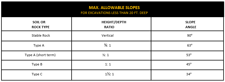
SLOPING, BRNCHING & SLOPE
SLOPE CONFIGURATION - TYPE A SOIL EXCAVATIONS
SIMPLE SLOPE – GENERAL
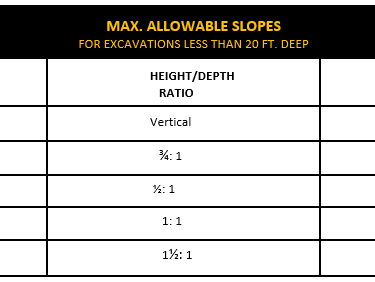
All simple slope excavations 20 ft. or less in depth must have a maximum allowable slope of ¾:1.
SIMPLE SLOPE - SHORT TERM
Simple slope excavations which are open 24 hrs. or less and which are 12 ft. or less in depth must have a maximum allowable slope of ½:1.
MULTIPLE BENCH
All benched excavations 20 ft. or less in depth must have an maximum allowable slope of ¾:1 and maximum bench dimensions as illustrated
UNSUPPORTED VERTICALLY SIDED LOWER PORTION MAXIMUM 8 FT. DEPTH
All excavations 8 ft. or less in depth which have unsupported vertically sided lower portions must have a maximum vertical side 3½ ft.
UNSUPPORTED VERTICALLY SIDED LOWER PORTION MAXIMUM 12 FT. DEPTH
All excavations more than 8 ft. but not more than 12 ft. in depth with unsupported vertically sided lower portions must have a maximum allowable slope of 1:1 and a maximum vertical side of 3½ ft.
SUPPORTED OR SHIELDED VERTICALLY SIDED LOWER PORTION
All excavations 20 ft. or less in depth which have vertically sided lower partitions that are supported or shielded must have a maximum allowable slope of ¾:1. The support or shield system must extend at least 18" above the top of the vertical side.

SLOPE CONFIGURATION - TYPE B SOIL EXCAVATIONS
SIMPLE SLOPE
All simple slope excavations 20 ft. or less in depth must have a maximum allowable slope of 1:1.
SINGLE BENCH
This bench allowed in cohesive soil only
MULTIPLE BENCH
All benched excavations 20 ft. or less in depth must have an maximum allowable slope of 1:1 and maximum bench dimensions as illustrated
VERTICALLY SIDED LOWER PORTION
All excavations 20 ft. or less in depth with vertically sided lower portions must be shielded or supported to a height at least 18’ above the top of the vertical side.
SLOPE CONFIGURATION - TYPE C SOIL EXCAVATIONS
SIMPLE SLOPE
All simple slope excavations 20 ft. or less in depth must have a maximum allowable slope of 1½: 1.
VERTICALLY SIDED LOWER PORTION
All excavations 20 ft. or less in depth with vertically sided lower portions must be shielded or supported to a height at least 18’ above the top of the vertical side. Must have a max. allowable slop of 1½:1.
ACTUAL SLOPE
The actual slope means the slope to which an excavation face is excavated.
The actual slope must not be steeper than the maximum allowable slope.
If there are signs of distress:
The actual slope must be less steep than the maximum allowable slope.
The slope must be cut back to an actual slope which is at least 1/2 horizontal to 1 vertical (1/2H: 1V) less steep than the maximum allowable slope.
When surcharge lads from stored material or equipment, operating equipment or traffic are present, a competent person must determine the degree to which the actual slope must be reduced below the maximum allowable slope and must assure that such reduction is achieved.
Surcharge loads from adjacent structures must be evaluated in accordance with the stability of adjacent structures.
TEMPORARY SPOIL
Temporary spoil must not be placed closer than 2 ft. from the surface edge of the excavation measured from the nearest base of the spoil to the cut.
This distance must not be measured from the crown of the spoil deposit.
Distance requirement ensures that loose rock of soil from the temporary spoil will not fall on employees.
Spoil should be placed so that it channels rainwater and other run off water away from the excavation.
Spoil should be placed so that it cannot accidentally run, slide or fall back into the excavation.
PERMANENT SPOIL
Permanent spoil should be placed at some distance from the excavation.
It's often created where underpasses are built or utilities are buried.
The improper placement of permanent spoil, such as insufficient distance from the working excavation, can make an excavation non-compliant with the horizontal-to-vertical ratio requirement for a particular excavation.
Permanent spoil can change undisturbed soil to disturbed soil and dramatically alter slope requirements.
INFO YOU MUST KNOW
Sloping or benching for excavations greater than 20 ft. deep must be designed by a registered professional engineer.
TERM ALERT
Actual slope: the slope to which an excavation face is excavated.
Maximum allowable slope: the steepest incline of an excavation face that is acceptable for the most favorable site conditions as protection against cave-ins and is expressed as the ratio of horizontal distance to vertical rise (H: V).
Short term exposure: a period of time less than or equal to 24 hrs. That an excavation is open.
Distress: means that the soil is in a condition where a cave-in is imminent or is likely to occur.
Evidence of soil distress:
development of fissures in the face of excavation of adjacent. to an open excavation
subsidence of the edge of an
slumping of material from the face or the bulging or heaving of material from the bottom of an excavation spalling of material from the face of an excavation
raveling: small amounts of material, ex. pebbles, suddenly separating from the face of an excavation and trickling or rolling down into the excavation
BENCHING
There are two basic types of benching, simple and multiple.
Soil type determines the horizontal to vertical ratio of the benched side.
As a general rule, the bottom vertical height of the trench must not exceed 4 ft. for the first bench.
Subsequent benches may be up to a max. of 5 ft. vertical in Type A soil and 4 ft. in Type B soil to a total trench depth of 20 ft.
All subsequent benches must be below the maximum allowable slope for that specific soil type.
For Type B soil the trench excavation is permitted in cohesive soil only.
SHORING TYPES - TIMBER, HYDRAULIC, PNEUMATIC
SHORING TYPES
Shoring is the provision of a support system for trench faces used to prevent movement of: Soil, roadway, foundation, underground utilities.
Shoring or shielding is used when the location or depth of the cut makes sloping back to the maximum allowable slope impractical.
Shoring systems consist of posts, wales, struts and sheeting.
Basic types of shoring: timber, hydraulic and pneumatic.
Design of shoring systems, shield systems or other protective systems that are drawn from manufacturer's tabulated data must be in accordance with all specifications, recommendations and limitations issued or made by the manufacturer. Deviation from specification is only allowed after the manufacturer issues specific written approval.
TIMBER SHORING
Timber shoring can be provided as a method of protection from cave-ins in trenches that do not exceed 20 ft. in depth.
Cal/OSHA provides 6 tables of information when using a timber shoring system, 2 for each soil type.
Determine the soil type or types in which the excavation is made and then select the appropriate table to select the size and spacing of the members.
The selection is based on the depth and width of the trench and on the horizontal spacing of the cross braces.
Where a choice of horizontal spacing of cross bracing is available, the horizontal spacing of the cross braces must be chosen before the size of any member can be determined.
Stable rock is exempt from shoring requirements.
HYDRAULIC SHORING
Hydraulic shoring uses a prefabricated strut and/or wale system manufactured of aluminum or steel
Provides a critical safety advantage over timber shoring because workers do not have to enter the trench to install or remove it.
Advantages of hydraulic systems:
are light enough to be installed by 1 worker
are gauge-regulated to ensure even distribution of pressure
can have their trench faces "preloaded" to use the soil's natural cohesion to prevent movement
can be adapted easily to various trench depths and widths.
All shoring should be installed from the top down and removed from the bottom up.
Hydraulic shoring should be checked at least once per shift for leaking hoses and/or cylinders, broken connections, cracked nipples, bent bases and any other damaged or defective parts.
TYPES OF HYDRAULIC SHORING
Vertical Aluminum Hydraulic Shoring with Spot Bracing
Uses a hydraulic cylinder to exert force against a vertical roll, which transfers the force to the wale.
Vertical Aluminum Hydraulic Shoring with Plywood
Adds plywood between the vertical roll and the wale.
Vertical Aluminum Hydraulic Shoring (Stacked)
Stacks multiple arrangements of the first type vertically.
Aluminum Hydraulic Shoring Water System (Typical)
Uses a hydraulic cylinder exerting force on a horizontal wale that presses against upright sheeting.
PNEUMATIC SHORING
Pneumatic shoring works similar to hydraulic shoring.
The primary difference is that pneumatic shoring uses air pressure instead of hydraulic pressure, an air compressor must be on site.
Pneumatic shoring uses upright sheeting, along with pneumatic/ hydraulic jacks and a screw jack. The various jacks press up against the wale, which in turn keep the shoring in position.
OTHER SHORING SYSTEMS
Screw Jacks
Screw jack systems differ from hydraulic and pneumatic systems in that the struts of a screw jack system must be adjusted manually.
Manually adjusting the struts creates a hazard because the worker has to be in the trench in order to adjust the struts.
Additionally, uniform "preloading" cannot be achieved with screw jacks and their weight creates handling difficulties.
Single-Cylinder Hydraulic Shores
Shores of this type are generally used in a water system, as an assist to timber shoring systems and in shallow trenches where face stability is required.
Underpinning
This process involves stabilizing adjacent structures, foundations and other intrusions that may have an impact on the excavation.
It's a procedure in which the foundation is physically reinforced.
Underpinning must only be conducted under the direction and with the approval of a registered professional engineer.
INFO YOU MUST KNOW
Use Tables C-1.1, C-1.2 and C-1.3, and Tables C-2.1, C-2.2 and C-2.3 for timber shoring systems.
For tables see Cal/OSHA.
SHIELDING SYSTEMS
SHIELDING TYPES - TRENCH BOXES
Trench boxes protect workers from cave-ins and similar incidents.
The excavated area between the outside of the trench box and the face of the trench must be as small as possible.
The space between the trench boxes and the excavation side are backfilled to prevent lateral movement of the box.
Shields may not be subjected to loads exceeding those which the system is designed for.
A trench shield consists of a knife edge, sidewall and struts.
The knife edge goes all the bottom edge of the sides of the trench shield and struts go between both sides of the shield to provide support.
SHIELDING TYPES - COMBINATION USE
Trench boxes are generally used in open areas, but can also be used in combination with sloping and benching.
The box must extend at least 18' above the surrounding area it there is sloping toward excavation.
The extension can be accomplished by providing a benched area adjacent to the box.
Earth can be excavated to a depth of 2 ft. below the shield if:
the shield is designed to resist the forces calculated for the full depth of the trench.
there are no indications while the trench is open of possible loss of soil from behind or below the bottom of the support system.
The conditions of this type require observation on the effects of bulging, heaving, boiling, surcharging, vibration, adjacent structures, etc., on excavating below the bottom of a shield.
Careful visual inspection of the listed conditions is the primary and best approach to hazard identification and control.
Shield configurations must comply with soil type slope requirements.
INFO YOU MUST KNOW
Designs of support systems. shield systems and other protective systems must be selected and constructed by the employer or the designee using OSHA Appendices, Manufacturer's Tabulated Data or having a registered professional engineer design it.
Employees must not be in shields when shields are being installed, removed or moved vertically.
EXCAVATION & TRENCH FACTS
RS (or RP) stands for Reference Stake.
Markings above and below the diagonal lines on a cut stake Indicate the amount of cut that is above the diagonal and the distance that is below it.
If RS distance is followed by a double line the remainder of the grade and distant should be established from the the grades setter’s RS hub.
The elevation on the side of the surveyor information stake is taken from the survey hup. It indicates the elevator of the surveyor’ hub above sea level.
The second horizontal line on a fill stake located 1 ft. above the finished grade is there to help the grade setter set the next fill stake.
West and east toe grades on a ditch channel stake indicate the bottom of the slope on each side of the channel.
“Setting Swedes" Is a method used for setting grade at a center point by sighting across 3 laths.
Most lasers are self-leveling.
A crows foot with a horizontal line drawn across it and an arrow with a circle through the tail pointing to that line, indicates the finished grade.
The finished line shows the grader operator the fill-up line.
Contour lines that are close together represent a steep slope.
Contour lines that connect to form a loop or a circle: represent a mound or a depression. Contour lines never change grade.
Start your measurements at a known elevation to correctly mark the cut/fill to produce the finish grade.
Only the last three numbers of the elevation show on the surveyor's rod. The excavation contractor might also set the grades for an industrial tract landscaping project.
When determining trench depth for laying pipe add the thickness of the pipe to the thickness of the pipe bedding to determine the amount of undercut.
The cutting edge on a scraper with an on board laser must be calibrated to a bench mark or know elevation. When setting a GPS station, the GPS receiver unit has to be set up plumb, level and in the same location every day to ensure reliable readings. .
When using GPS, you should be able to access at least 5 satellites to ensure the accuracy of the signal.
The difficult part of using GPS is the initial base unit set up and model building. The primary cost-cutting feature of concrete curb machines is that there is not form brew needed. * An auger-driven curt machine uses as grade the asphalt base it runs on.
The number of scrapers you'll need is determined by the length of the haul.
The front scraper on push-pull scrapers should always load first, while the back scraper pusher.
Use a paddies-wheel scraper when the When the job calls for shallow cuts.
The best equipment for cutting a rocky slope is a dozer with a slope bar.
Water tanks cut the fill time more than 50% over a standpipe.
Erosion control measures must always be in place during the rainy season and whenever there’s a threat of rain.
A grizzly is used to compact fill.
Tolerance of a fill slope: ± 0.5 ft.
Slope tolerance of a rocky slope: 2 ft.
0.33 ft. is equal to 4”.
The amount of compaction measures the density of the soil.
Never fill against an undisturbed slope
A haul road must be maintained smooth and wide.
A dozer may not be needed it working in good soil.
A contour plan is also known as a Topographic plan.
A bench mark is a point of known elevation.
A profile graph is basically a straightedge on wheels.
A profile graph is used to check the road grade.
Always round the surveyor’s cut up to the even foot.
A slip form paver s used to pour concrete roadways.
It's good practice to overbuild a fill slope by 6” to 8”.
Compaction reqs. for sidewalk & curb subgrade: 90%.
A 2% slope will rise and fall a 0.40 ft. distance in 20ft.
Compaction requirement for street sub-grade: 95%.
A profile machine can mill concrete and asphalt surfaces.
Lasers set close to level will level themselves.
Lasers bumped off level will automatically shut off.
Slide the receiver up or down if the receiver unit is not receiving a signal from the laser level.
A laser unit showing a straight bar indicates that the receiver is on lever.
When checking a road section with a laser, the grade setter needs to mark 3 elevations on the lath: finished asphalt, finished aggregate and finished sub-grade.
The grizzly is a screen or several bars that allow only chunks of the correct size to pass through a recycle and kicks large chunks of asphalt back to the grinding unit to be reground to size * The purpose of carbide teeth on a trencher is to have the trencher dig through hard materials.
A concrete slip-form paver produces a smooth concrete mat that needs a tined finish.
The center of the transmitter of a laser must be pointed in a line parallel with the trench to be excavated.
Typical loading time for an open- bowl scraper being pushed under average conditions: 30 seconds. The scraper should apply little or no power while being pushed, letting the dozer do the work.
The scraper operator must open the apron wider when loading ripped rock versus dirt.
The biggest advantage of using a compactor on rock fill is that it helps grind down sharp rock points preventing tire damage.
Using experienced equipment operators is one of the best ways to Keep your costs down.
The compactor operator must keep dozing dirt as he/she works in order to mix the moisture evenly.
In rough excavation, grade and maintain a smooth haul and grade new haul roads as the cut moves.
During rough excavations the only area trimmed to finish grade is the lot pad.
During rough grading, overbuild the building pads 0.05ft. to 0.10 ft. for trim excess.
A glue-down curb or extruded curb can only be placed on top of finished asphalt
If the island curb is a barrier curb that sits on or below subgrade, place it before the aggregate and paving.
Before any excavation can be placed in a fill area, the area must be ripped, watered and compacted. Commercial building pads are overbuilt 5 ft.
Make the rough grading of parking areas easier by excavating through the Island noses.
When the Initial excavation is completed, have the surveyor check the pads and parking areas to certify that they're excavated property. It's best to rip and compact the parking sub-grade before the curbs are poured.
Areas in the building pad with unsuitable soil must be excavated before any pad fill is placed.
A 1:1 slope is very difficult for a grader to cut because it's too steep for the grader to run on.
When building a road till those chokers, the road subgrade should be left low for the choker excess.
Sprinkler lines are cut or damaged during the road widening preparation process, they must be quickly repaired to prevent water running onto the project.
Over fill the shoulder to gain extra fill width for equipment.
Always build the outside edge of a fill higher.
Channels are usually staked every 50ft. on both sides.
In a residential area it is best to use utility-supplied power and submersible electric pumps.
After stripping and clearing, the grader or dozer rips the original ground where the new fill will be placed so it can be watered and compacted.
The amount of compaction measures soil density.
If trench bottom is soft undercut it to get a stable base.
Gravel under precast manhole bottom: 1ft. min.
Before any work begins on a highway project the foreman and grade setter should go over the plans and slaking.
The right-of-way stakes usually define. The limits of the work area.
Work and equipment can travel beyond the right-of-way stakes only with the property owner's written permission.
If the grade stakes are not set on the right-of-way line, the line will be staked separately at 100-foot intervals.
Double horizontal lines marked on a survey stake mean “and then".
When building a large slope, the grade setter should set fill slope stakes in a straight line at a 90ª angle to the surveyor’s stakes.
When building a large slope, grade setter must set fill slope stakes in a straight line at 90° angle to the surveyor’s stakes.
Narrow embankments are more difficult to build than wide embankments.
A paddle-wheel scraper is the most efficient equipment for stripping.
Delineators or cones with reflective tape are preferred over flashers.
There are 3 methods used to tie out manholes, water valves and cleanouts.
When removing shoulder asphalt, make 2 saw cuts at the edge of the pavement to protect the saw cut from traffic damage.
Mailboxes on posts that are in the work area should be cut off and placed in 5 gallon buckets tiled with gravel so they can easily be removed out of the way as excavation begins.
Cut the roadside ditch must before beginning a road excavation.
The choice of excavating equipment for a road section depends primarily on where the excess dirt must be hauled.
The first fill on a narrow road widening is the material generated by the bench cut.
Cut a bench into the existing slope to provide a good lie-in for the new fill.
Material that has heavy clay chunks can get hung up in bottom dump trucks.
If filing from the road above, scrape and sweep the road-bed clean each night before the lane is re-opened for traffic.
A pad foot compactor with a center wheel is last and very effective on a narrow fill.
A diversion trench should be dug from downstream to upstream.
When using a pumping setup, install a float switch system to be sure the water is maintained at the proper level.
Use a hoe with a compaction wheel to fill in narrow, washed-out slopes.
Aggregate compacts more easily.
The grader operator must cut only 1 fl. Behind the curb.
In large parking lots you can use both end and bottom dumps.
Lime mixing/spreading temperatures: 35°F and above.
3% to 5% of lime is added to soil for the lime treatment.
3 passes of the lime machine are usually enough to mix the lime into the subgrade.
For best results, begin trimming the lime-treated soil no more than 12 hrs.
Some agencies won’t allow you to use vibratory rollers on lime base soil.
In soil with high sand content use cement treatment instead of lime treatment.
When ground water is a problem, use a well point pumping system to control the water level.
Wait at least 24 hrs. to place the top lift after plugging a soft area with asphalt.
Best equipment for removing unsuitable soil in a thin bridged area: hoe.
Use a trapezoid bucket for slop trenching.
The main reason for using filter fabric is to keep from penetrating the aggregate.
Rolling will not help stable an unsuitable subgrade.
Plastic or steel gas main are less likely to be broken by equipment working in unsuitable areas.
Gas, electrical and telephone lines usually require 6 to 1 ft. of sand placed around them.
Be sure the sand is watered down well for compaction.
The most important element for achieving good soil compaction is the amount of water used.
Nuclear testing is faster than sand cone testing.
A nuclear test gauge will indicate tightly-compacted soil by showing a low reading on the gauge.
Before taking a compaction test on an embankment fill in progress, the grader or compactor should cut down 8” to level spot for testing.
Use a pad-drum vibratory self-propelled roller or pad-wheeled compactor to roll the subgrade on large jobs.
Never use a smooth-drum vibratory roller on a large dirt fill being built.
The grade setter must first set boots at each surveyor’s hub if no string line has been set, before he/she can check grade with an eye level.
When a barrier curb is staked for forming, the hub is offset 2 ft. from the top-back-of-curb.
When a concrete machine is used for a Type 2 of type 1-A curb there should be a 3 it. offset.
If the concrete machine pours over an undercut subgrade it will fill the undercut with concrete.
Rough subgrade should be left 0.05 ft. to 010 ft. high to account for shrinkage.
When processing subgrade with extremely dry soil, it may be necessary for the grader to tum (or blade) the soil over several times.
Before trimming, be sure that the grader has a good cutting edge with no worn ends.
If the grader is not equipped with slope control or so the grader operator has something to sight to while making his first trim pass along the curb.
When each bank plug has only one nail, it indicates that the road has a constant super, which is a continuous slope in one direction.
When trimming subgrade on a road project with no curbs, carry the grade by setting a string line down each side of the road to run sonar on.
If gravel or aggregate is overworked, it will lose fines.
Water keeps the aggregate fines attached to the rocks so they won't separate as easily.
Common tool for setting hubs in parking lot: Swedes.
When dumping aggregate with bottom dumps, gravel should be spread 100 ft.
It takes about 15 ft. from the time the dump person gives the dump signal until the trailer gate actually opens to begin the gravel dump.
The first step in lime treatment is to rip up the road surface or parking area to be limed.
Ensure an even flow through a long detour channel by setting huts and cuts for grade.
An unsuitable area is an area that is too soft to cover with base rock or asphalt.
When paving, the acceptable temperature range for asphalt is 285°F to 350°F.
Open graded asphalt should not be placed when the weather drops below 60°F.
Complete the final compaction of cement-treated base within 2 hours of mixing.
A profiler efficiently removes an old road surface.
Manholes are vacuum-tested to 1 pound of pressure.
The maximum neck height allowed on a manhole is 18 including the casting.
Stab rod. checks the depth/thickness of the asphalt.
When rolling asphalt, the first pass must be made on the low side of the asphalt mat.
The usual spread rate for chips when chip sealing is 15 Ibs. to 30 Ibs. per square yard.
Removing unsuitable material below the sub-grade during excavation must be billed as extra work.
Line under drain trench with construction fabric.
Pull shield along the trench by a hoe when laying pipe.
A Vermeer trencher is used for hardpan and rock.
The maximum neck height allowed on a manhole is 18” including the casting.
Under drains are placed where seepage is expected. which is usually on the low side of the load.
INJURY & ILLNESS PREVENTION PROGRAM
IIPP & INFORMATION ABOUT JOB HAZARDS
Every employer must have and maintain an effective Injury and Illness Prevention Program (IPP).
Employees must not be required or permitted to work in an unsafe place, unless the purpose is to make it safe.
Prior to starting work, the employer must survey the job site to determine and safeguard against hazards.
Only qualified persons can operate equipment/machinery.
Every employer must have a suitable number of trained and available staff to render first aid.
A first aid kit must be present at each workplace.
Employees must be given instructions regarding job hazards, safety precautions and the employer's Code of Safe Practices upon being hired.
Post a written Code of Safe Practices in a conspicuous location at each job site office or provide each supervisory employee with a copy of the Code of Sale Practices.
Employees assigned new job assignments require training,
Employees subjected to known or new job site hazards, must be instructed in identification, protection and first aid procedures.
Periodic, scheduled inspections must be conducted.
"TOOLBOX"/"TAILGATE" MEETINGS
Supervisors must conduct toolbox' or "tailgate" safety meetings with their crews every 10 working days.
INSPECTION
Daily inspections of excavations, adjacent areas and protective systems must be made by a competent person for evidence of situations that could result in:
cave-ins
indications of failure of protective systems
hazardous atmospheres and conditions
An inspection must be conducted by the competent person prior to the start of work and as needed throughout the shift.
Inspections must also be made after every rain storm or other occurrence that can increase the possibility of a hazard.
Inspections are required when employee exposure is anticipated.
If evidence of a situation that could result in a possible hazardous is found, all exposed employees must be removed from the hazardous area until the necessary precautions have been taken to ensure their safety.
Encourage employees to report unsafe conditions, assure them that they won't get in trouble for reporting the problem and that the problem will be corrected.
REPORTING TO DOSH
Employers must immediately report the following to the nearest DOSH district by telephone or other immediate contact method.
any work-related fatality
any work-related serious injury
any work-related illness
'immediately' means as soon as practically possible, but not longer than 8 hours after the employer knows of, or, with diligent inquiry would have known of, the incident.
'Serious injury or illness," in general, means any injury or illness that requires inpatient hospitalization for a period of more than 24 hours for other than medical observation, or in which an employee suffers a loss of any member of the body or suffers any serious degree of permanent disfigurement.
Employers must report to the nearest DOSH district any operation involving carcinogens, asbestos, lead or other hazardous material.
Construction of trenches or excavations 5 ft. or more deep, into which a person is required to descend require a permit from the DOSH.
SPECIAL HEALTH & SAFETY CONSIDERATIONS
SURFACE ENCUMBRANCES
All surface encumbrances must be removed or supported to safeguard employees, it they create a hazard.
WARNING SYSTEM FOR MOBILE EQUIPMENT
A warning system must be used when mobile equipment is operated adjacent to an excavation or when such equipment is required to approach the edge of an excavation and the operator does not have a clear and direct view of the edge of the excavation.
Warning systems include: barricades, hand or mechanical signals or stop logs.
It possible, the grade should be away from the excavation.
PROTECTION FROM WATER ACCUMULATION HAZARDS
Employees must not work in excavations where there is accumulated water, or in which water is accumulating, unless adequate precautions are taken.
Precautions include: special support or shield systems to protect from cave ins. water removal to control the level of accumulating water or use of a safety harness and lifeline.
Water removal equipment and operations must be monitored by a competent person.
If excavation work interrupts the natural drainage of surface water (ex. streams), diversion ditches, dikes or other suitable means must be used to prevent surface water from entering the excavation and to provide adequate drainage of the area adjacent to the excavation.
Excavations subject to runoff from heavy rains require an inspection by a competent person and compliance with Sections
1511 (h)(1) & (h)(2).
FALL PROTECTION
Walkways or bridges with standard guardrails must be provided where employees or equipment are required or permitted to cross over excavations over 6 feet in depth and 30' in width.
Adequate barrier physical protection must be provided at all remotely located excavations.
All wells, pits, shafts, etc., must be barricaded or covered.
Upon completion of exploration and similar operations, temporary wells, pits, shafts, etc., must be backfilled.
EXPOSURE TO FALLING LOADS
No employee is permitted underneath loads handled by lifting or digging equipment.
Employees must stand away from any vehicle being loaded or unloaded to avoid being struck by any spillage or failing materials.
Operators can remain in the cabs of vehicles being loaded or unloaded when the vehicles are equipped to provide adequate protection for the operator during loading and unloading operations.
EXPOSURE TO VEHICULAR TRAFFIC
Employees exposed to public vehicular traffic must be provided with and must wear, warning vests or other suitable garments
marked with or made of reflectorized or high-visibility material.
PROTECTION FROM LOOSE ROCK OR SOIL
Protection must be provided to protect employees from loose rock or soil that could pose a hazard by falling or rolling from an excavation face. Protection includes:
scaling to remove loose material.
installing protective barricades at intervals as on the face to stop and contain falling material.
Employees must be protected from excavated or other materials or equipment that could pose a hazard by falling or rolling into excavations. Protection includes:
placing and keeping such materials or equipment at least 2 ft. from the edge of excavations.
using retaining devices.
ACCESS & EGRESS
A stairway, ladder, ramp or other safe means of egress must be located in trench excavations 4 ft. or more in depth.
A stairway, ladder, ramp or other safe means of egress must require no more than 25 ft. of lateral travel for employees.
Structural ramps that are used solely by employees as a means of access or egress from excavations must be designed by a competent person.
Structural ramps used for access or egress of equipment must be designed by a competent person qualified in structural design.
Structural ramps must be constructed in accordance with the design.
Ramps and runways constructed of 2 or more structural members must have the structural members connected together to prevent displacement.
Structural members used for ramps and runways must be of uniform thickness.
Cleats or other appropriate means used to connect runway structural members must be attached to the bottom of the runway or must be attached in a manner to prevent tripping.
Structural ramps used in lieu of steps must be provided with cleats or other surface treatments to the top surface to prevent slipping.
HAZARDOUS ATMOSPHERES
Must comply with the requirements set forth in the Construction Safety Orders and the General Industry Safely Orders.
Atmospheres of excavations greater than 4 ft. in depth where oxygen deficiency or a hazardous atmosphere exists must be tested before employees enter the excavation.
Employees must be provided with proper respiratory protection or ventilation in atmospheres containing less than 19.5% oxygen.
Proper ventilation must be provided, to prevent employee exposure to an atmosphere containing a concentration of a flammable gas in excess of 20% of the lower flammable limit of the gas.
When controls are used to reduce the level of atmospheric contaminants to acceptable levels, testing must be conducted as often as necessary to ensure that the atmosphere remains safe.
Emergency rescue equipment, such as breathing apparatus, a safety harness and line, or a basket stretcher, must be readily available where hazardous atmospheric conditions exist or may reasonably be expected to develop during work in an excavation.
Employees entering bell-bottom pier holes, or other similar deep and confined footing excavations, must wear a harness with a lifeline securely attached to it.
Whenever internal combustion engine driven equipment is operated inside a shaft a ventilation system must be provided.
Build your own dreams
Or someone else will hire you to build theirs. Here is how you can take action – starting today.